Thermoforming DFM Design Guide
Part Dimensional Design
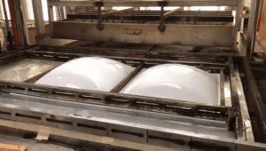
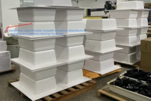
Thermoforming involves stretching two-dimensional flat plastic sheets into complex three-dimensional geometric shapes1 (imagine: inflating a balloon into Hello Kitty shape).
Subsequently, the wall thickness of the finished part will be less than the original sheet thickness, as the stretch ratio and depth-to-width ratio vary throughout the part.
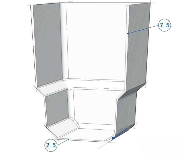
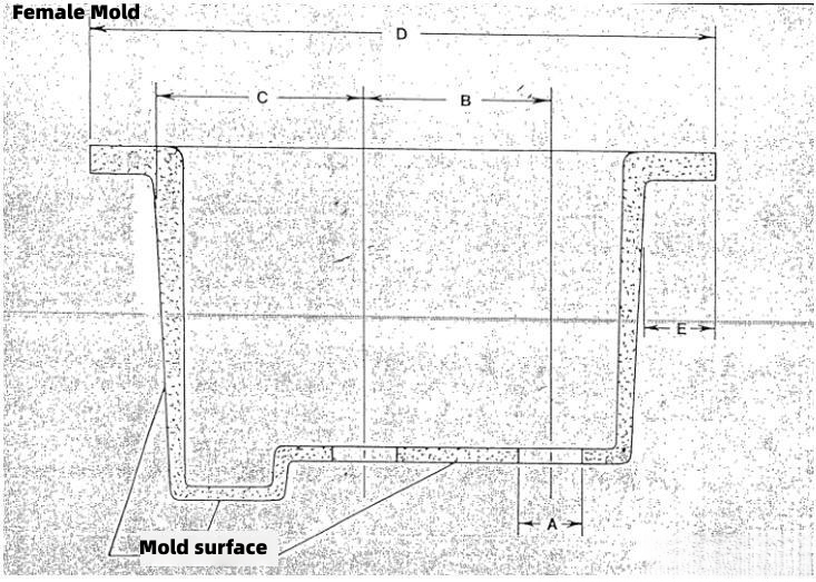
Therefore, when designing thermoformed part dimensions, all dimensions must be marked on the side that contacts the mold, while the other side is difficult to control.
If thermoforming uses a male mold (plug), dimensions are marked on the inside of the part. If thermoforming uses a female mold (cavity), dimensions are marked on the outside of the part.
Stretch Ratio
The stretch ratio is the ratio of the total surface area of one side of the finished thermoformed part to the surface area of the initial plastic sheet.
Generally speaking, the stretch ratio cannot exceed 3:1.
Depth-to-Width Ratio
The depth-to-width ratio is the ratio of the depth at the deepest point of the finished thermoformed part to the minimum opening distance.
Generally speaking, the depth-to-width ratio cannot exceed 1:12.
Corner Radii
At wall-to-wall connections, corner radii or chamfers need to be added to avoid sharp corner designs. This is most important for three-way intersections at the deepest points.
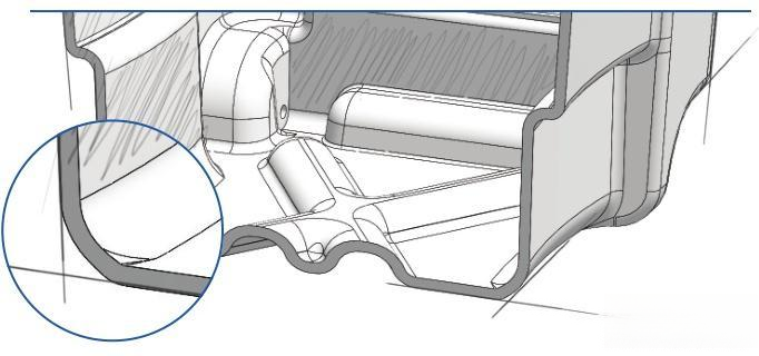
The larger the corner radius, the better the wall thickness uniformity in various regions of the part and the better the part strength.
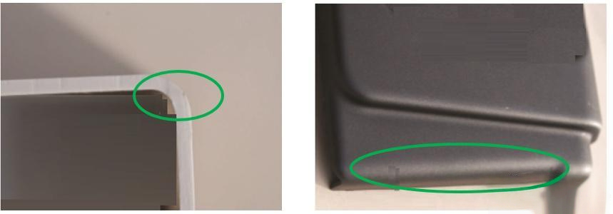
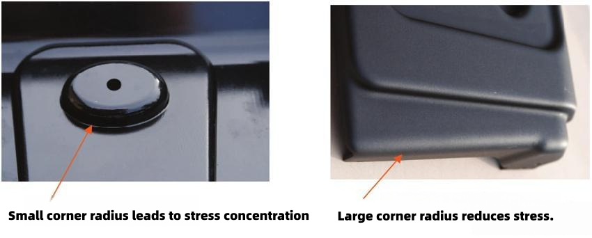
If the corner radius is too small, it can easily cause excessive wall thinning at corners, low strength, and stress concentration. Generally speaking, to avoid stress concentration, the corner radius should be at least 75% of the wall thickness at that location.
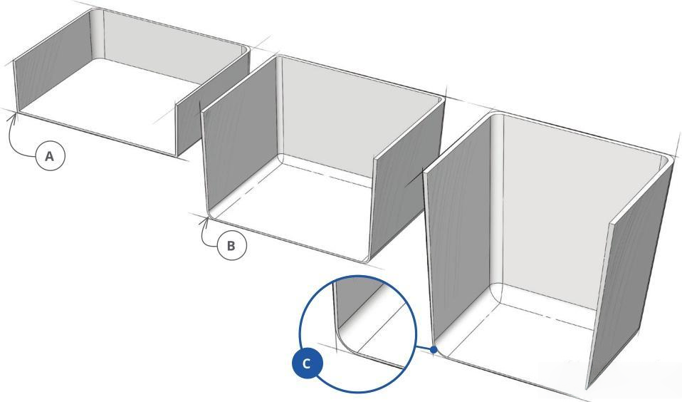
The deeper the part, the larger the required minimum corner radius.
| Depth Range (mm) | Minimum Corner Radius (mm) |
|---|---|
| 0 ~ 76.2 | 0.381 ~ 3.175 |
| 76.2 ~ 152.4 | 3.175 ~ 6.35 |
| 152.4 ~ 304.8 | > 6.35 |
The size of the minimum corner radius is related to the plastic material. Compared to PC and PE, ABS and PVC allow smaller minimum corner radii.
The size of the minimum corner radius is related to the type of thermoforming process. Compared to vacuum forming, pressure forming allows smaller minimum corner radii3. Therefore, pressure forming is commonly used for parts with more complex structural shapes.
When permitted, the larger the corner radius, the better.
Undercuts
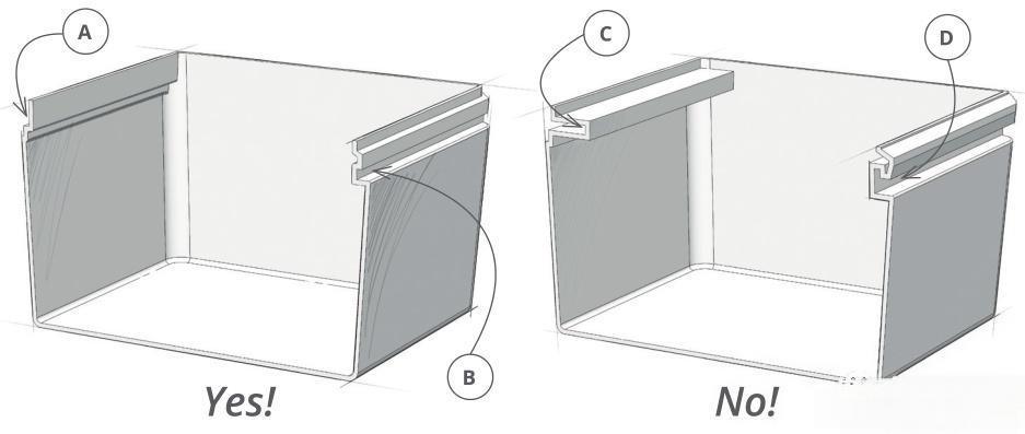
Undercuts are valuable features on thermoformed parts, used to increase part strength, provide snap-fit functionality and fixing features, and hide trimming marks, etc.
Undercuts need to be designed correctly to avoid undercuts that are too narrow or cannot be released from the mold.
Draft Angles
To enable parts to be smoothly released from the mold, certain draft angles need to be designed.
- For parts formed using male molds (plug), the draft angle is 4°~6°4
- For parts formed using female molds (cavity), the draft angle is 1.5°~2°5
- 0° draft angle is also possible, but the mold requires complex motion structures
If the part surface has texture, or the part structure is more complex, the draft angle needs to be increased.
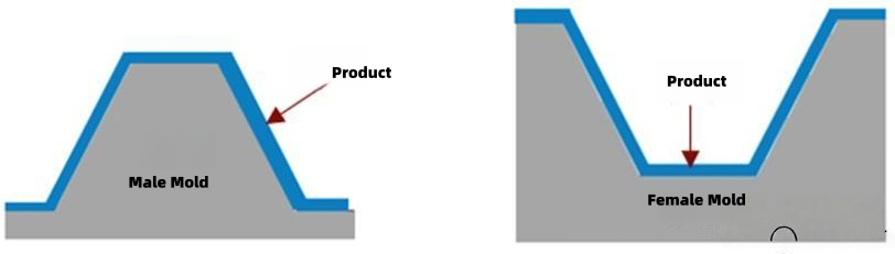
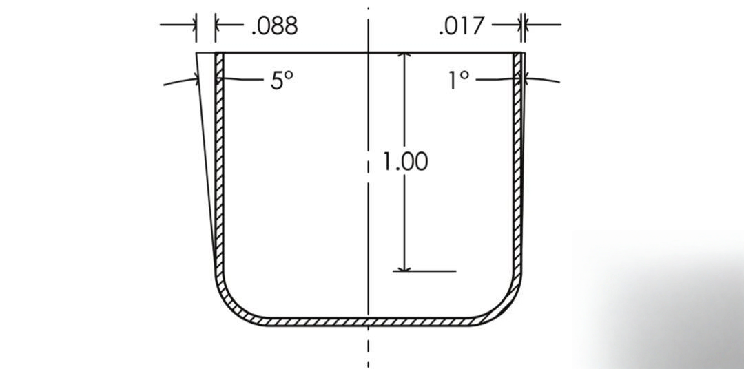
Compared to female molds (cavity), male molds (plug) require larger draft angles because plastic shrinkage will grip the male mold tightly.
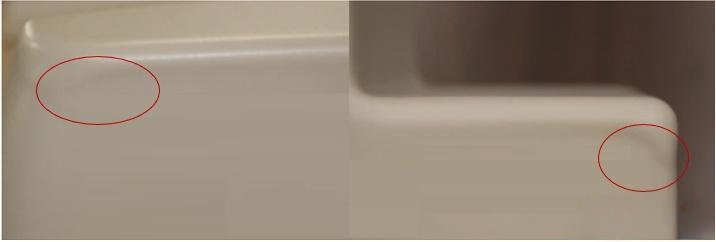
If the draft angle is too small, when the plastic sheet stretches in the mold, the first contact point cools faster, which reduces plastic flowability6, preventing uniform material distribution and causing wrinkles on the part surface.
Ribs
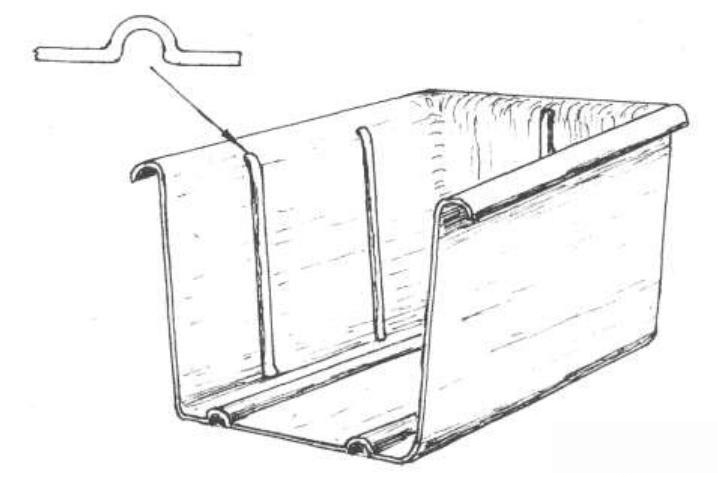
Ribs are used to increase the strength of thermoformed parts.
The design structure of ribs for thermoformed parts differs from injection molded parts and needs to be designed as shown:
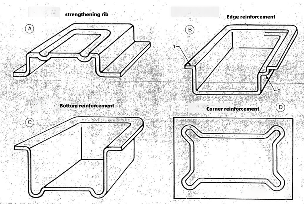
- The outer width of the rib must be at least 1.75 times the depth of the rib7
- The thicker the wall thickness, the wider the rib width requirement
- For pressure forming, the distance between ribs should be at least 1 times the rib depth. The greater the air pressure, the wider the distance
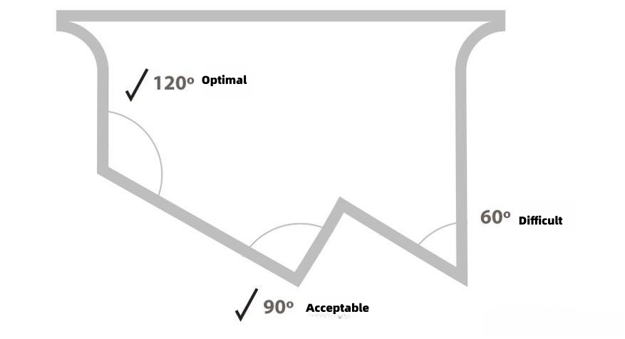
Wall-to-Wall Angles
In the vertical cross-section of the part, the larger the angle between walls, the better.
Tolerances
The general tolerance standards for thermoforming are shown in the table below:
Thermoforming Tolerances
| Characteristic | Tooling Dimension <305mm | Explanation |
|---|---|---|
| Thermoforming Characteristic | ±0.508mm | For dimensions exceeding 305mm, an additional tolerance of 0.0254mm is added for every 25.4mm increment |
| Deformation/Warping | ±0.762mm/305mm | - |
CNC Trimming Tolerances
| Feature | Tolerance | Explanation |
|---|---|---|
| Trim Hole Diameter | ±0.127mm | Hole ≤ 25.4mm |
| Trim Hole Diameter | ±0.254mm | 25.4mm < Hole < 76.2mm |
| Trimming Slot | +0.254mm | Trimming Slot ≤ 25.4mm |
| Trimming Slot | ±0.508mm | 25.4mm < Trimming Slot |
| CNC Trimming Edges | ±0.508mm | Hole > 7.62mm |
"Thermoforming - Wikipedia", https://en.wikipedia.org/wiki/Thermoforming. Thermoforming is a manufacturing process in which a thermoplastic sheet is heated to a pliable temperature, formed to a specific shape using a mold, and trimmed to create a usable product. Evidence role: definition; source type: encyclopedia. Supports: the basic principle of the thermoforming manufacturing process. ↩
"Draw Ratio in Thermoforming: How It Controls Wall ...", https://rapidmade.com/draw-ratio-in-thermoforming-how-it-controls-wall-thickness-strength-and-part-quality/. Thermoforming design references commonly specify 1:1 as a general maximum depth-to-width ratio for conventional vacuum forming, with variations possible using pressure assist or plug assist methods. Evidence role: general_support; source type: education. Supports: typical depth-to-width ratio constraints in thermoforming design. Scope note: Advanced forming techniques may achieve higher ratios with appropriate material and equipment ↩
"Designing for Thermoforming: From the Design Guide — Chapter 2", https://www.rayplastics.com/designing-thermoforming-design-guide-chapter-2/. Pressure forming applies compressed air (typically 50-100 psi) in addition to vacuum, forcing material more tightly against mold surfaces and enabling sharper details, tighter corner radii, and more complex geometries than vacuum forming alone. Evidence role: general_support; source type: education. Supports: the enhanced detail reproduction capability of pressure forming compared to vacuum forming. ↩
"Understanding draft in thermoforming - Profile Plastics, Inc.", https://thermoform.com/blog/understanding-draft-in-thermoforming/. Thermoforming design guides typically recommend draft angles of 3° to 5° or higher for male molds, with the exact requirement depending on material type, part depth, and surface texture. Evidence role: general_support; source type: education. Supports: typical draft angle requirements for male mold thermoforming. Scope note: Specific angle recommendations vary across sources and depend on multiple design factors ↩
"Draft Angle - an overview | ScienceDirect Topics", https://www.sciencedirect.com/topics/engineering/draft-angle. Female mold thermoforming generally requires smaller draft angles than male molds, typically in the range of 1° to 3°, because thermal contraction pulls the part away from the cavity surface rather than gripping it. Evidence role: general_support; source type: education. Supports: typical draft angle requirements for female mold thermoforming. Scope note: Exact requirements vary with material properties and part geometry ↩
"Cooling Process in Thermoforming Machines | GtmSmart", https://www.gtmsmartmachine.com/cooling-process-in-thermoforming-machines.html. In thermoforming, areas of the heated sheet that contact the mold first experience rapid cooling, which increases viscosity and restricts further material flow, potentially leading to non-uniform thickness distribution and surface defects. Evidence role: mechanism; source type: education. Supports: the effect of differential cooling on material flow during thermoforming. ↩
"Thermoforming Design Considerations - Empire West", https://www.empirewest.com/thermoforming-design-considerations.html. Thermoforming rib design requires wider base dimensions relative to depth compared to injection molding, with guidelines suggesting width-to-depth ratios of 1.5:1 or greater to ensure adequate material distribution and prevent excessive thinning. Evidence role: general_support; source type: education. Supports: dimensional ratios for rib design in thermoformed parts. Scope note: Specific ratios vary with material type and forming method ↩