Thermoforming DFM Design Guide
A comprehensive design for manufacturability reference for thermoformed plastic parts -- covering geometry, tolerances, and process constraints.
2.1 Part Dimensional Design
Thermoforming involves stretching two-dimensional flat plastic sheets into complex three-dimensional geometric shapes (imagine: inflating a balloon into Hello Kitty shape). Subsequently, the wall thickness of the finished part will be less than the original sheet thickness, as the stretch ratio and depth-to-width ratio vary throughout the part.
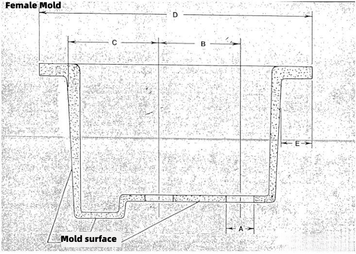
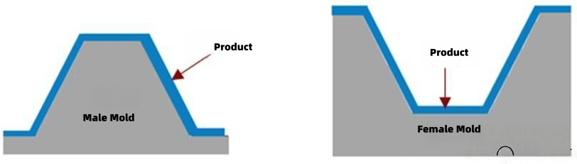
Therefore, when designing thermoformed part dimensions, all dimensions must be marked on the side that contacts the mold, while the other side is difficult to control.
Male Mold
Dimensions are marked on the inside of the part.
Female Mold
Dimensions are marked on the outside of the part.
2.2 Draw Ratio
The draw ratio is the ratio of the total surface area of one side of the finished thermoformed part to the surface area of the initial plastic sheet.
Generally speaking, the stretch ratio cannot exceed 3:1.
2.3 Depth-to-Width Ratio
The depth-to-width ratio is the ratio of the depth at the deepest point of the finished thermoformed part to the minimum opening distance.
Generally speaking, the depth-to-width ratio cannot exceed 1:1.
2.4 Corner Radii
At wall-to-wall connections, corner radii or chamfers need to be added to avoid sharp corner designs. This is most important for three-way intersections at the deepest points.
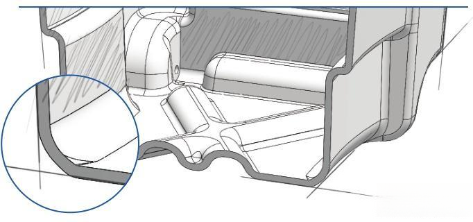
The larger the corner radius, the better the wall thickness uniformity in various regions of the part and the better the part strength.
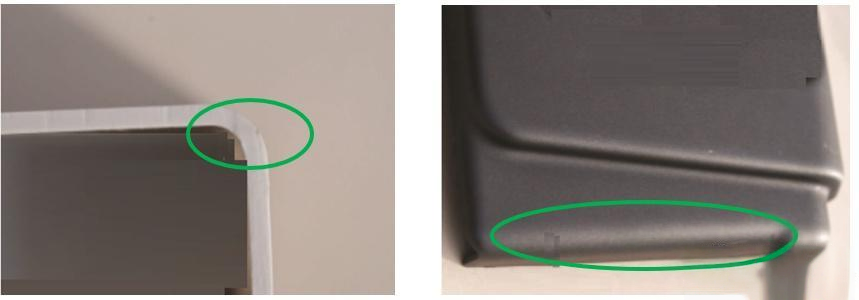
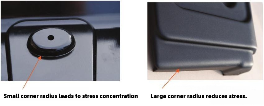
Minimum corner radius Rule
If the corner radius too small, it can easily cause excessive wall thinning at corners, low strength, and stress concentration. To avoid stress concentration, the corner radius should be at least 75% of the wall thickness at that location.
The deeper the part, the larger the required minimum corner radius.
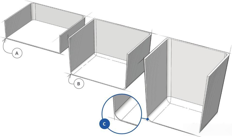
| Part | Depth (mm) | Minimum Corner Radius (mm) |
|---|---|---|
| A | 0 ~ 76.2 | 0.381 ~ 3.175 |
| B | 76.2 ~ 152.4 | 3.175 ~ 6.35 |
| C | 152.4 ~ 304.8 | > 6.35 |
Material Influence
Compared to PC and PE, ABS and PVC allow smaller minimum corner radii.
Process Influence
Compared to vacuum forming, pressure forming allows smaller minimum corner radii -- commonly used for complex structural shapes.
Best Practice: When permitted, the larger the corner radius, the better.
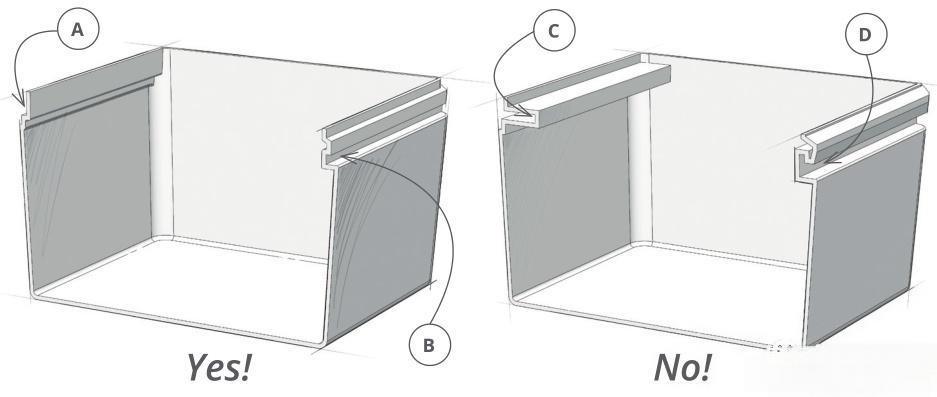
2.5 Undercuts
Undercuts are valuable features on thermoformed parts, used to increase part strength, provide snap-fit functionality and fixing features, and hide trimming marks, etc.
Undercuts need to be designed correctly to avoid undercuts that are too narrow or cannot be demolded.
External undercut
Double undercut
Too narrow
Cannot be demolded
2.6 Draft Angles
To enable parts to be smoothly released from the mold, certain draft angles need to be designed.
Male Mold
Larger angle required
Female Mold
Smaller angle sufficient
Zero Draft
Requires complex mold motion
If the part surface has texture, or the part structure is more complex, the draft angle needs to be increased.
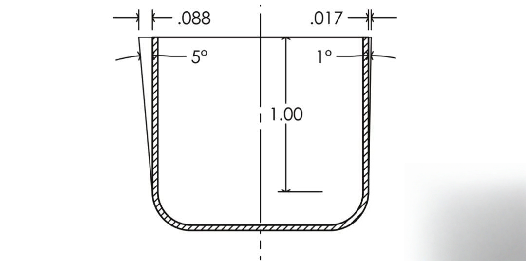
Compared to female molds, male molds require larger draft angles because plastic shrinkage will grip the male mold tightly.
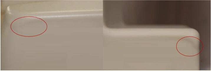
Insufficient Draft Angle Risk
If the draft angle is too small, when the plastic sheet stretches in the mold, the first contact point cools faster, reducing plastic flowability, preventing uniform material distribution and causing wrinkles on the part surface.
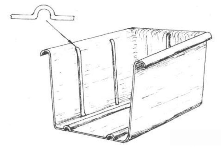
2.7 Ribs
Ribs are used to increase the strength of thermoformed parts.
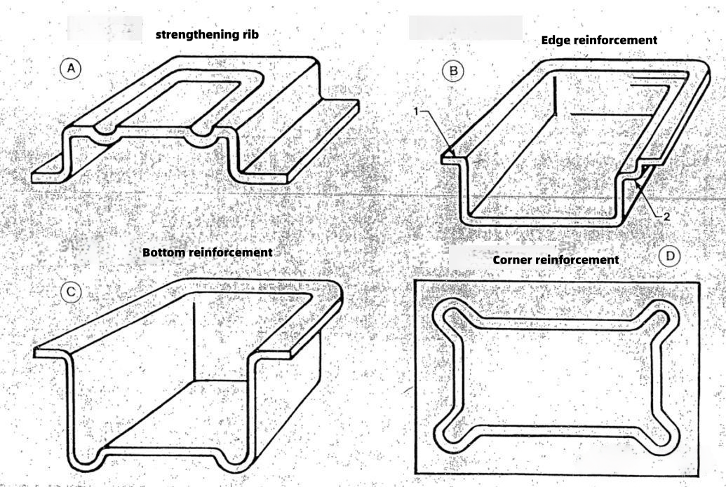
The design structure of ribs for thermoformed parts differs from injection molded parts and needs to be designed as shown:
-
The outer width of the rib must be at least 1.75× the depth of the rib.
-
The thicker the wall thickness, the wider the rib width requirement.
-
For pressure forming, the distance between ribs should be at least 1× the rib depth. The greater the air pressure, the wider the required distance.
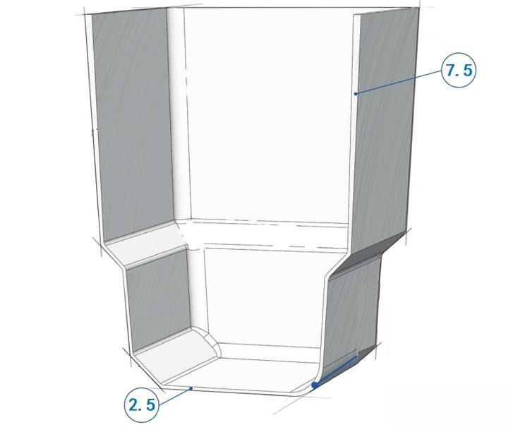
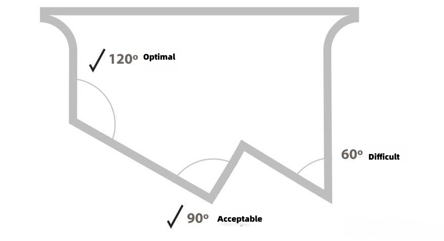
2.8 Wall-to-Wall Angles
In the vertical cross-section of the part, the larger the angle between walls, the better.
Best Practice: Maximize the angle between adjacent walls in the vertical cross-section.
2.9 Tolerances
The general tolerance standards for thermoforming are shown in the table below:
| Thermoforming Characteristic | Tooling Dimension <305mm | Explanation |
|---|---|---|
| Thermoforming Characteristic | ±0.508mm | For dimensions exceeding 305mm, an additional tolerance of 0.0254mm is added for every 25.4mm increment. |
| Deformation/Warping | ±0.762mm/305mm |
CNC Trimming Tolerance standards are shown in the table below:
| Characteristic | Tolerance Value | Explanation |
|---|---|---|
| Trim Hole Diameter | ±0.127mm | Hole ≤ 25.4mm |
| ±0.254mm | 25.4mm < Hole < 76.2mm | |
| Slot | +0.254mm | Slot ≤ 25.4mm |
| ±0.508mm | 25.4mm < Slot | |
| CNC Trimming Edges | ±0.508mm | Hole > 7.62mm |